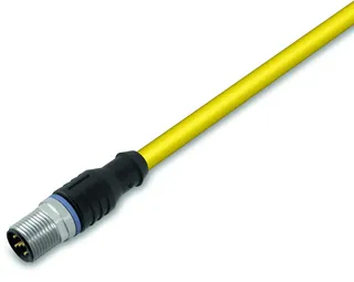
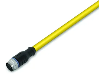
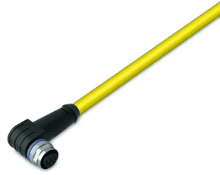
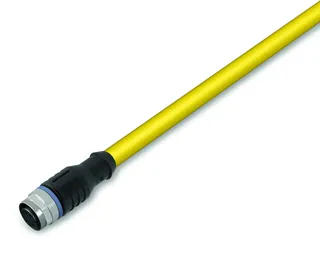
Wago
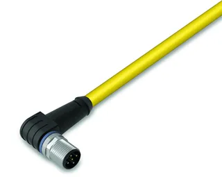
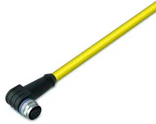
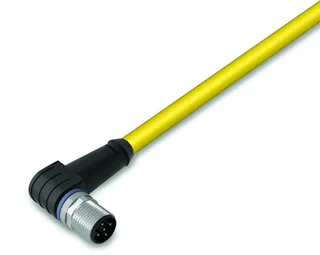
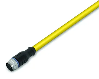
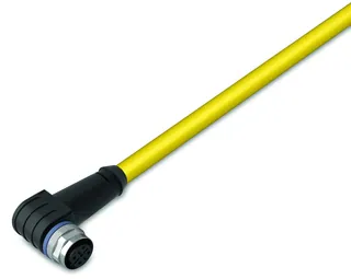
767-5204
1 / 4
- Part Number
- 767-5204
- Tariff Code
- 85389099990
- UPC
- 4050821643425
- Get up to 90 days payment terms from 500+ suppliers
- Reselling discounts up to 40%!
Send request for price
1
Payment methods:
Environmental Requirements
- Ambient temperature (operation)
- -25 … +60 °C
- Ambient temperature (storage)
- -40 … +85 °C
- Protection type
- IP67
- Protection class
- III
- Relative humidity (without condensation)
- 95 %
- Vibration resistance
- 5g per IEC 60068-2-6
- Shock resistance
- Short-term: 50g/11 ms/half-sine per IEC 60068-2-27; Long-term: 30g/6 ms/half-sine per IEC 60068-2-29
- EMC immunity to interference
- Per EN 61000-6-2
- EMC emission of interference
- Per EN 61000-6-4
Connection Data
- Connection technology: inputs/outputs
- 2 x M12 socket; A-coded; 5-pole; shielded; 2 x M12 socket; A-coded; 5-pole; shielded
- Connection technology: field supply
- 1 x M12 plug; 4-pole; A-coded; 1 x M12 socket; 4-pole; A-coded
- Connection technology: system supply
- 1 x M12 socket; 4-pole; A-coded; 1 x M12 plug; 4-pole; A-coded
- Connection technology: system bus
- 1 x M12 socket, 5-pole, B-coded, shielded; 1 x M12 plug, 5-pole, B-coded, shielded
- Connection requirement (permissible cable length)
- 15 m
- Connection requirement (permissible cable length) (2)
- 200 m
- Connection requirement (permissible cable length) (3)
- 30 m
- Connection requirement (permissible cable type)
- RS-232
- Connection requirement (permissible cable type) (2)
- RS-485
- Connection requirement (permissible cable type) (3)
- Digital inputs: unshielded
Physical Data
- Width
- 50 mm / 1.969 inches
- Height
- 35.7 mm / 1.406 inches
- Depth
- 117 mm / 4.606 inches
Material Data
- Color
- Light gray
- Housing material
- Polyamide (PA), Makrolon (address switch cover), flammability per UL94-V0, halogen/silicon-free
- Fire load
- 0.010 MJ
- Weight
- 265.000 g
- Conformity marking
- CE
Technical Data
- Communication
- MOVILINK® interface
- Number of digital inputs
- 4
- Number of digital outputs
- 4
- Number of configurable digital inputs/outputs
- 4
- Sensor connection
- 4 x (2-wire, 3-wire)
- Actuator connection
- 4 x (2-wire, 3-wire)
- Input characteristic
- High-side switching || Type 2, per IEC 61131-2
- Input filter
- Hardware: ≤ 110 µs; Software: parameterizable
- Input current per channel for signal (0) max.
- 2.5 mA
- Input current per channel for signal (1) typ.
- 7.3 mA
- Input current per channel for signal (1) min.
- 6.4 mA
- Input current per channel for signal (1) max.
- 7.5 mA
- Input voltage (note)
- 24 VDC (-3 VDC < UIN < +30 VDC); Power from UA strongly recommended, recovery for voltages > UA
- Output characteristic
- High-side switching
- Output current per channel
- 0.5 A
- Output current (module)
- 2 A
- Leakage current in OFF state
- 5 µA
- Switching frequency (max.)
- 20 Hz; Inductive load
- Switching frequency (max.) (2)
- 500 Hz; Resistive load
- Switching frequency (max.) (3)
- 500 Hz; Lamp load
- Output voltage
- ≤ UA
- Output protection
- Short circuit/overload protection (thermal shutdown)
- Voltage range for signal (0)
- −3 … +5 VDC
- Voltage range for signal (1)
- 11 VDC … UA
- Load type of switching frequency
- Inductive load
- Baud rate
- 9.6 kBd … 57.6 kBd
- Transmission channels
- 1 RxD / 1 TxD (half duplex)
- Process data width
- Interface: 10-byte input/output data; DIO: 1-byte input/output data + 1-byte status
- Parameterizable functions
- I/O diagnostics (per module): Short circuit/overload (sensor/actuator supply); Undervoltage (ULS + UA) || I/O diagnostics (per channel): Overtemperature || Operating mode (per module): Easy mode; Mailbox mode || Operating mode (per channel): RS-232; RS-485 || Baud rate (per channel): 9,600 … 57,600 Baud || Data bits (per channel): 8
- Protection
- Reverse voltage protection for ULS + Uo; Short circuit protection for sensor/actuator supply
- Parity
- Even
- Number of stop bits
- 1
- Output resistance
- 0.4 Ω
- Supply voltage (system and sensor)
- 24 VDC(-25 … +30 %); Logic and sensors (ULS)
- Current consumption (system and sensor)
- 75 mA
- Supply voltage (field)
- 24 VDC (-25 … +30 %); Actuators (UA)
- Current consumption, field supply (module with no external load)
- 25 mA
- Isolation
- 500 V supply/system bus
- Indicators
- LED (F) red: Error status; LED (SB) green/red/orange: System bus status; LED (ULS, UA) green: Power supply status; LED (Ch1.1, Ch2.1) yellow/red: Transmission status; LED (Ch1.2, Ch2.2) yellow/red: Reception status; LED (0 … 3) yellow/red: Status DI/DO 1 … DI/DO 3; Non-retentive displays
- Current carrying capacity (supply connections)
- 8 A
- Drop-out time from “1” to “0”
- Typ. 45 µs (resistive load)
- Connection of 2-wire BEROs
- Admissible closed current: 1.5 mA (max.)
- Rise time from “0” to “1”
- Typ. 60 µs (resistive load)
- Output operation
- Non-retentive
- Resistance to recovery
- ≤ 1 A (error: 1 channel)
- Voltage drop against UA
- 0.2
- S-bus (system bus) disruption
- 0 V status
Specifications
- Product Group Code
- 0015
Commercial Data
- Packaging type
- Box
- Country of origin
- DE
- GTIN
- 4050821643425
- Customs tariff number
- 85389099990
Other Categories
ActuatorsBlocksCables, Pipes & HosesCompressorsControlCouplings & FittingsCylinders & PistonsElectronicsFiltersHVACIndustrial PC's & HMIsLightingLinear techniqueMotorsPower SupplyPower TransmissionPumps & ValvesRenewable energyRoboticsSeals, Rings & ConnectorsSensors & Measuring DevicesTools and AccessoriesCNCOther
